Strata Motor
A High Torque Motor is designed to produce strong turning force, even when a machine moves slowly or carries a heavy load. Torque describes rotational force, while speed describes how quickly the shaft turns. These values are related, but they are not interchangeable. A motor can spin rapidly and still struggle with a demanding application.
This guide explains how high torque motors create motion through electromagnetic interaction. Current flows through the stator windings and produces a magnetic field. That field interacts with the rotor, creating shaft rotation. In many systems, electronic controllers regulate current to improve starting force, speed control, and efficiency. Some designs also use gearboxes to increase output torque. The trade-off is reduced output speed.
Real systems are messier. Friction, heat, voltage drops, and changing loads affect performance. A motor that performs well on a workbench may behave differently inside a conveyor, robotic joint, or electric vehicle. Engineers therefore examine rated torque, peak torque, duty cycle, thermal limits, and control quality before choosing a motor. Manufacturer data and practical testing matter more than impressive marketing figures.
Small details matter. A warm housing may indicate normal operation, poor cooling, or excessive load. The answer is not always obvious. This article explores motor construction, operating principles, common applications, selection factors, and typical limitations. It also questions a common assumption: higher torque is not automatically better. The best motor matches the load, speed, control system, operating environment, and expected service life.
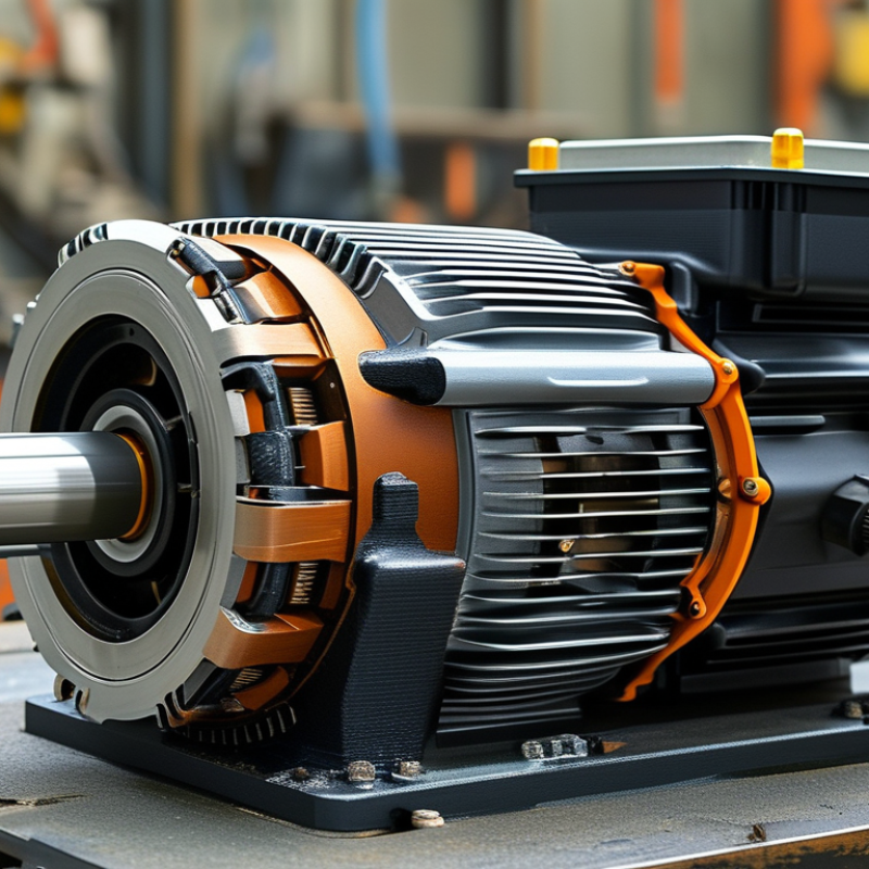
A high-torque motor produces strong rotational force, especially at low speed. Torque is rotational force. It helps equipment start, lift, turn, or hold heavy loads without stalling. Unlike a motor designed mainly for high speed, this motor prioritizes mechanical strength and controlled movement. Its core features include a powerful magnetic circuit, durable windings, and a shaft built to resist twisting. A suitable gear reduction system can multiply output torque, although it usually lowers speed.
The motor works by sending electrical current through coils, creating a magnetic field around the rotor. Interaction between the rotor and stator fields creates rotation. In practical systems, sensors may measure position or speed, while a controller adjusts current to maintain stable torque. This response matters when a conveyor starts with a full load or a robotic joint pauses under pressure. Engineers also check continuous torque, peak torque, voltage, efficiency, and heat limits before selecting a motor. Heat is the trade-off. High current can create substantial heat, reducing service life if cooling is inadequate. The phrase “high torque” is not perfectly standardized, so comparing only catalog labels can mislead. Real performance depends on speed, duty cycle, gearing, load inertia, and operating temperature. A motor that performs well during a short test may struggle during hours of repeated acceleration. Careful testing remains essential.
A high torque motor produces strong turning force, especially at low speed. Torque begins with current flowing through energized windings. Those windings create a magnetic field inside the stator. The rotor’s magnets, or magnetic field, react with it. This interaction creates force along the rotor’s circumference. That sideways force turns the shaft. Torque is roughly force multiplied by radius. A larger effective radius can increase torque without simply increasing current. The exact result depends on motor geometry, magnetic material, and winding design.
In a practical motor, the controller changes current timing as the rotor moves. This keeps the magnetic pull slightly ahead of the rotor. The angle matters. If the fields align completely, turning force can fall sharply. With correct timing, each energized coil produces a useful tangential pull. More current usually creates more torque, but only until resistance, heat, saturation, or controller limits intervene. This is where specifications need careful reading. A stated peak torque may last seconds, while continuous torque must survive longer operation.
I have found that load tests reveal more than labels. A motor may start a heavy mechanism, then slow when its winding temperature rises. Back electromotive force also increases with speed, opposing the applied voltage and reducing available current. Gear reduction can multiply shaft torque, though it trades speed for force. The simple explanation is useful, but incomplete. Friction, bearing alignment, and cooling can change the real result. Engineers should measure current, speed, temperature, and torque under the intended load, not only on an unloaded bench.
What Is a High Torque Motor and How Does It Work?
Key Components That Control High-Torque Performance
A high-torque motor produces strong rotational force, often at low speed. Its core relationship is straightforward: torque increases with magnetic flux and current. The stator creates the rotating magnetic field. The rotor responds and generates mechanical output. Windings, magnets, and the air gap control this interaction. A smaller air gap can improve magnetic coupling, but manufacturing tolerances become more demanding. The IEA reported that electric motor systems consumed 43–46% of global electricity in its motor-driven systems analysis.
The controller is equally important. An inverter regulates current frequency, voltage, and phase angle. This prevents sudden torque loss during heavy starting loads. Position sensors can improve timing, especially below base speed. However, sensors add cost and another failure point. Bearings support the rotor and reduce friction. A gearbox may multiply output torque, but it also introduces backlash, noise, and efficiency losses. The motor housing and cooling path remove heat from copper and iron losses. Without effective cooling, high current becomes a short-term advantage.
The U.S. Department of Energy has estimated that motor-driven equipment can consume 60–70% of industrial electricity. That figure makes efficiency more than a laboratory concern. In field testing, a motor may meet its rated torque but still struggle with poor alignment or unstable supply voltage. Datasheets cannot reveal every installation problem. Engineers should test temperature, vibration, current, and speed under the actual load. The model helps. Reality still needs checking.
| Key Component or Factor | Primary Function | How It Controls High-Torque Performance | Relevant Engineering Data | Design Considerations |
|---|---|---|---|---|
| Motor Torque Constant | Defines the torque produced for a given motor current. | For many electric motors, electromagnetic torque is approximately proportional to current: T ≈ Kt × I. | Torque T is measured in N·m, current I in A, and torque constant Kt in N·m/A. | A higher torque constant can reduce the current required for a given torque output. |
| Stator Core | Provides the magnetic path and supports the electromagnetic field that produces rotation. | A larger active iron volume and optimized magnetic circuit can increase torque capability before magnetic saturation occurs. | Torque is influenced by active length, air-gap radius, magnetic flux density, and current loading. | Excessive flux density can cause saturation, increasing losses without providing proportional torque. |
| Rotor and Shaft | Transmit electromagnetic torque to the mechanical load. | A rigid rotor minimizes torsional deflection and maintains the intended air gap during high-load operation. | Mechanical stress depends on transmitted torque, shaft diameter, material strength, and operating speed. | The shaft must withstand both continuous torque and short-duration peak torque without permanent deformation. |
| Windings and Conductors | Carry current and generate the magnetomotive force that creates torque. | More effective copper area can support higher current, while winding configuration affects torque constant, resistance, and voltage requirements. | Copper loss is approximately Pcu = I²R, where R is winding resistance. | High current increases torque but also produces significantly more heat because copper loss rises with the square of current. |
| Permanent Magnets or Field System | Establishes the magnetic field that interacts with the stator field. | Stronger and better-positioned magnetic flux can increase torque per ampere and improve torque density. | Air-gap flux density is commonly expressed in tesla; the practical value is limited by magnetic saturation and thermal conditions. | Magnet temperature, demagnetization resistance, mechanical retention, and air-gap uniformity are critical. |
| Air Gap | Separates the rotor from the stator while allowing magnetic coupling. | A smaller, uniform air gap generally improves magnetic coupling and torque production. | Air-gap dimensions are typically specified in millimetres and must account for manufacturing tolerances and thermal expansion. | An overly small gap can cause rubbing, vibration, or failure when the rotor shifts under load. |
| Motor Controller and Inverter | Regulates phase current, voltage, commutation, and direction of rotation. | Accurate current control determines available torque, while appropriate commutation keeps the magnetic fields correctly aligned. | Peak torque is limited by allowable phase current, inverter current rating, bus voltage, and control strategy. | Current limiting protects the windings and power electronics during acceleration or stalled conditions. |
| Position Sensor or Estimation System | Provides rotor position information for precise electronic commutation and torque control. | Accurate position feedback helps maintain the correct torque angle, especially at low speed and during rapid load changes. | Position accuracy is commonly specified in electrical or mechanical degrees, depending on the motor system. | Sensorless control may reduce hardware but can be less reliable at zero or very low speed. |
| Bearings and Mechanical Support | Maintain rotor alignment and carry radial or axial loads. | Low-friction, properly preloaded bearings reduce mechanical losses and help preserve a consistent air gap. | Bearing selection depends on radial load, axial load, speed, operating temperature, and expected service life. | Misalignment or insufficient lubrication can increase vibration, heat, and torque demand. |
| Thermal Management | Removes heat generated by copper, iron, mechanical, and power-electronic losses. | Effective cooling allows the motor to sustain higher current and torque without exceeding insulation or magnet temperature limits. | Continuous torque is usually lower than short-term peak torque because it is limited by temperature rise. | Cooling may use conduction, forced air, or liquid circulation depending on power density and duty cycle. |
| Gearbox or Torque Multiplier | Trades motor speed for higher output torque at the mechanical interface. | Ideal output torque is approximately Tout ≈ Tmotor × ratio; actual torque is reduced by gearbox losses. | Output power remains approximately conserved apart from losses: P = T × ω. | Gear ratio, efficiency, backlash, lubrication, noise, and shock-load capacity must match the application. |
| Duty Cycle | Describes how long and how often the motor operates at different load levels. | A motor may deliver a high peak torque briefly but require a lower continuous torque to control temperature over extended operation. | Important ratings include continuous torque, peak torque, overload duration, speed, and rest or cooling intervals. | Application sizing should use the actual torque-speed profile rather than peak torque alone. |
| Torque-Speed Relationship | Describes how available torque changes as motor speed increases. | Many motors provide a current-limited constant-torque region at lower speed and a voltage-limited region where torque decreases as speed rises. | Mechanical power follows P = T × ω, where angular speed ω is measured in rad/s. | Motor selection must consider starting torque, operating speed, acceleration time, and load inertia. |
Key principle: High torque is produced by combining sufficient magnetic flux with controlled current and a mechanically robust structure. Continuous high-torque operation is ultimately limited by heat removal, insulation temperature, magnetic material limits, mechanical stress, and the motor's duty cycle.
A high-torque motor produces strong turning force, even when a machine moves slowly. Its operation starts with an electrical command from a controller. The controller sends current through coils inside the stator. This current creates a changing magnetic field around the rotor. The rotor responds to that field and begins to turn. More current usually creates more torque. Not magic.
As the rotor turns, magnetic attraction and repulsion continue around the stator. The controller changes current timing to maintain smooth rotation. A position sensor reports the rotor’s angle, speed, and direction. The controller uses this feedback to adjust power several times per second. When the load suddenly increases, current rises to protect motion. This response is not always perfect. A delayed signal can cause vibration, noise, or uneven movement.
The generated torque then travels through the motor shaft to the machine. Some systems use gear reduction to increase output force and reduce speed. Direct-drive designs transfer torque without traditional gears, but they may require larger motors. During testing, technicians check shaft load, temperature, current, and vibration. A warm housing can indicate overload, poor cooling, or incorrect settings. Heat matters. In practical installations, small alignment errors can also waste torque and shorten service life. A careful engineer allows for these limitations instead of trusting theoretical ratings alone.
What Is a High Torque Motor and How Does It Work?
A high torque motor produces strong rotational force, especially at low speed. This helps equipment start heavy loads without sudden movement. Its electromagnetic field converts electrical energy into controlled shaft rotation. Gear reduction, larger windings, or stronger magnets can increase output torque. However, torque figures alone can mislead. Starting torque, continuous torque, and peak torque describe different operating conditions.
Common applications include conveyors, hoists, winches, robotic joints, electric vehicles, and industrial mixers. Conveyors may need high starting torque when fully loaded. Hoists require controlled torque to prevent load drop during acceleration. The International Energy Agency’s Energy Efficiency 2023 report states that electric motor systems consume about half of global electricity. This makes correct motor selection important for both reliability and energy use. The U.S. Department of Energy also identifies motor-driven systems as a major industrial electricity consumer.
Tips: Check load torque, speed range, duty cycle, ambient temperature, and available voltage. Size for real startup conditions, not average load data. Allow thermal margin, but avoid excessive oversizing. A larger motor is not always safer; it may operate inefficiently at light loads. Review acceleration time and braking needs with a qualified engineer. Small oversights matter. Instruments and field measurements often reveal assumptions that calculations miss.
Representative engineering ranges for common applications. Actual motor selection depends on speed, duty cycle, acceleration, load inertia, and thermal limits.
A high-torque motor produces substantial rotational force at relatively low or moderate speed. Applications with high starting loads, frequent acceleration, vertical lifting, or variable resistance require sufficient continuous torque as well as short-term peak torque. When selecting a motor, compare the required load torque and speed with the motor’s torque-speed curve, then verify overload capacity, gearbox ratio, efficiency, cooling, control method, and operating duty.
: Current flows through stator windings and creates a magnetic field. The rotor reacts to this field and turns the shaft. Torque depends on current, magnetic strength, and effective radius. Not magic.
High torque helps start heavy mechanisms without requiring high rotational speed. It can move belts, shafts, or loaded machinery from a standstill. Starting performance may change as the motor heats.
The controller changes current timing as the rotor moves. It keeps the magnetic field slightly ahead of the rotor. Correct timing creates a useful sideways pull. Timing matters.
More current usually increases torque, but only within practical limits. Resistance creates heat, and magnetic saturation can reduce further gains. Controller limits may also restrict current. More is not always better.
Peak torque may last only a few seconds during starting or brief overloads. Continuous torque must remain safe during extended operation. A motor can reach its peak rating, then slow as temperatures rise. Ratings need careful reading.
As speed increases, back electromotive force rises inside the windings. This opposing voltage reduces available current from the supply. The motor may then produce less torque at higher speed. The simple explanation is incomplete.
Gear reduction can multiply output torque while reducing shaft speed. It may also introduce backlash, noise, friction, and efficiency losses. The final torque depends on gear ratio and mechanical efficiency. Force trades for speed.
Test torque, current, speed, winding temperature, vibration, and shaft alignment. Use the intended load instead of relying only on an unloaded bench. A warm housing may indicate overload or poor cooling. Reality still needs checking.
A High Torque Motor is designed to deliver strong rotational force, especially when starting, accelerating, or driving heavy loads. Unlike a motor focused mainly on high speed, it prioritizes torque output, efficiency, and stable performance under demanding conditions. Torque is generated through the interaction between magnetic fields in the stator and rotor. When electrical current flows through the motor windings, it creates a magnetic field that attracts and repels the rotor, producing continuous rotation. The amount of torque depends on factors such as current, magnetic strength, winding design, motor size, and operating speed.
Key components, including the rotor, stator, windings, bearings, housing, and control system, work together to manage high-torque performance. During operation, the controller supplies power, the magnetic field develops, the rotor turns, and the motor transfers force through its shaft. High-torque motors are commonly used in industrial equipment, robotics, vehicles, lifting systems, and automation. Selecting the right model requires considering load size, starting torque, speed range, duty cycle, power supply, efficiency, cooling, and installation conditions.
